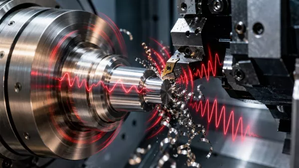
In modern CNC machining, micrometers matter. Advanced machine tools, precision cutting tools, and carefully prepared programs make it possible to manufacture components with extremely high accuracy. However, even the best machine can encounter a problem that cannot be solved simply by using more precise control systems.
That problem is vibration generated during cutting.
Sometimes, its presence is revealed by a characteristic high-pitched sound coming from the machine. In other cases, the first warning signs are deteriorating surface quality, accelerated tool wear, or difficulties maintaining the required dimensional tolerances.
Interestingly, vibrations can occur even when the machine is in good working condition, the tool is properly secured, and the machining parameters appear to have been selected correctly.
Why does this happen? The answer lies in the dynamics of the cutting process and the interactions between the machine tool, fixture, workpiece, and cutting tool.
Imagine a modern CNC lathe capable of positioning a tool with extremely high accuracy. Its control system continuously monitors the movements of individual axes, while the machining program precisely defines the toolpath.
It might seem that this is enough to produce a perfect component.
In reality, the situation is more complicated.
During turning, milling, or drilling, the tool applies a certain force to the material. This force causes small deformations in the components of the machining system. At the same time, the conditions of contact between the cutting edge and the material, the thickness of the material being removed, and the load on the tool all change.
If the system is sufficiently rigid and stable, these deformations remain under control. However, under unfavorable dynamic conditions, small vibrations can begin to amplify.
High machine positioning accuracy does not automatically guarantee high machining accuracy under load.
This is why CNC machining processes must be considered as interactions between several interdependent components.
Manufacturing engineering uses the concept of the Machine–Fixture–Workpiece–Tool (MFWT) system.
This simplified model describes the components involved in the cutting process and their influence on its stability.
Each component performs a specific function.
The machine tool's structure provides the necessary rigidity, vibration damping, and precise guidance of machining movements.
Important factors include:
A heavy machine tool with a well-designed structure can more effectively limit unwanted displacement. However, this does not mean that machine mass alone solves every problem.
Its dynamic characteristics, or the way it responds to changing loads, are equally important.
The fixture or holder provides the connection between the tool or workpiece and the machine.
In turning operations, secure clamping of both the workpiece and the cutting tool is particularly important. In milling, the quality of the toolholder also plays a major role.
Even a highly rigid machine cannot provide the expected stability if the fixture lacks sufficient rigidity or fails to ensure proper clamping.
Clearance, incorrect clamping pressure, or excessive tool overhang can significantly change the behavior of the entire system during machining.
The workpiece itself can also be a source of dynamic problems.
Particularly challenging components include:
Under cutting forces, such workpieces may deform and vibrate.
Furthermore, their rigidity may change during machining because material removal affects the component's geometry and mass.
The cutting edge transmits the forces generated during chip formation.
Stability is influenced by factors such as cutting-edge geometry, tool material, wear condition, and the length of the tool extending from its holder.
The last parameter is particularly important.
A long, slender tool is more susceptible to deflection than a shorter tool of similar design.
Consequently, maintaining stability when machining deep holes or hard-to-reach surfaces can be significantly more difficult than during standard operations.
A simple experiment helps explain this phenomenon.
Imagine a metal rod rigidly fixed at one end. If its unsupported section is short, bending it is difficult. However, as the unsupported length increases, the same rod becomes much easier to deflect.
Cutting tools behave in a similar way.
In a simplified cantilever beam model, deflection under a transverse force increases proportionally to the cube of the length.
This means that doubling the tool overhang can increase deflection by as much as eight times, assuming all other conditions in the model remain unchanged.
That is an enormous difference.
In practice, the actual behavior of a cutting tool also depends on toolholder rigidity, clamping method, cross-sectional geometry, and material properties.
Nevertheless, the principle remains extremely important: the shorter and more rigid the path through which cutting forces are transmitted, the easier it is to maintain process stability.
This is why experienced CNC process engineers try to keep tool overhang to the minimum necessary.
Not every vibration indicates a malfunction or abnormality.
Small, natural vibrations occur during cutting as a result of the interaction between the tool and the material. Problems arise when their amplitude becomes excessive or they begin to adversely affect the machining process.
Two particularly important types of vibration can be distinguished.
Forced vibrations occur as a result of external or periodically varying forces.
Possible sources include:
An example is milling, where successive cutting edges periodically enter and leave the cutting zone.
The resulting load variations excite vibrations in the machine structure.
If the excitation frequency approaches one of the system's natural frequencies, resonance may occur, causing a significant increase in vibration amplitude.
A much more complex phenomenon is self-excited vibration, commonly known as chatter.
Its characteristic feature is that vibration can increase due to feedback between tool and workpiece vibrations and changing cutting forces.
How does this happen?
During machining, tool vibrations leave small irregularities on the surface. During the next pass of the cutting edge, these irregularities alter the instantaneous thickness of the material being removed.
This, in turn, changes the force acting on the tool.
The varying force generates further vibrations, which affect the shape of the next machined surface.
Under certain conditions, these phenomena begin to reinforce one another.
As a result, even initially small vibrations can quickly reach a level that makes proper machining impossible.
This explains why a machine may operate smoothly at one spindle speed but begin producing a characteristic, piercing sound after only a slight adjustment to the machining parameters.
Self-excited vibrations are among the most important limitations on the productivity of cutting processes.
Their consequences extend far beyond noise.
Characteristic wavy marks, regular patterns, or surface irregularities may appear on the machined component.
For parts requiring excellent surface quality, even minor disturbances may make additional finishing operations necessary.
A vibrating tool does not follow its intended path precisely relative to the workpiece.
This can lead to dimensional and geometric errors, including problems maintaining roundness, cylindricity, or the required surface profile.
Unstable contact between the cutting edge and the material produces fluctuating mechanical loads.
Under unfavorable conditions, microchipping of the cutting edge, accelerated wear, and even damage to the insert or entire tool may occur.
When the process becomes unstable, it is often necessary to reduce cutting parameters, change the tool, or redesign the operation.
Each such situation creates additional time requirements and costs.
The problem can be particularly serious in mass production because even a small amount of time lost on one component is repeated across hundreds or thousands of subsequent parts.
Intuition suggests that the faster a machine operates, the greater the risk of vibration.
In reality, the relationship is not that simple.
In the case of self-excited vibrations, process stability may change nonlinearly with spindle speed.
This means that a particular process may be unstable at one speed, stable at a slightly higher speed, and then unstable again after another parameter adjustment.
Why?
Because what matters is not only the magnitude of the cutting force but also the frequency and phase of the vibrations, as well as the way successive cutting-edge passes interact with the previously machined surface.
This is why reducing spindle speed is not always the solution.
Sometimes, a carefully selected increase in speed can improve process stability.
However, this is not a universal method. Every adjustment must account for the limitations of the tool, material, machine, and cutting conditions.
One of the most interesting tools used in cutting dynamics analysis is the stability lobe diagram.
These diagrams help identify parameter ranges in which the process is more likely to operate without self-excited vibrations.
They most commonly illustrate the relationship between spindle speed and the limiting depth of cut.
The characteristic shape of the curves resembles a series of lobes or tongues.
This is where the English term stability lobe diagram comes from.
Such a diagram helps answer several important questions:
Developing these diagrams involves analyzing the system's dynamic characteristics, tool properties, and data describing cutting forces.
Therefore, a stability lobe diagram is not a universal parameter table suitable for every machine.
A diagram prepared for one combination of machine, tool, and clamping arrangement may not accurately represent the conditions at another workstation.
Rigidity is frequently discussed when analyzing cutting processes. It is extremely important, but it is not the only parameter determining stability.
Vibration damping is equally significant.
This can be illustrated by comparing two objects that behave differently after being struck.
One continues to resonate for a long time, gradually losing energy. The other stops vibrating quickly.
Similar differences occur in machine and tool structures.
Two systems with comparable rigidity may exhibit different dynamic behavior if their ability to dissipate vibration energy differs.
This is why modern machining technology employs solutions designed to improve damping, such as specially engineered machine structures and vibration-damped boring bars.
This is particularly important when machining deep holes, where using a short, highly rigid tool is often impossible.
Thin-walled components are among the most demanding workpieces.
In many industries, designers aim to reduce component weight while maintaining the required strength. This results in structures featuring thin walls, ribs, and delicate geometric features.
Machining such components requires special attention.
Imagine a thin-walled sleeve clamped in a lathe chuck.
During cutting, the force acting on the tool also causes deformation of the workpiece. If the wall is sufficiently thin, its displacement may affect the actual depth of cut.
Furthermore, as material is removed, the sleeve's dynamic properties change.
Parameters that provided stable operation at the beginning of the process may no longer be equally effective near the end.
In such cases, the following factors are important:
Sometimes, removing material in several stages is more effective than performing a single aggressive pass.
The objective is not only to reduce vibration but also to minimize deformation and maintain the required geometry of the finished component.
An experienced CNC operator can often identify warning signs before the machining operation is complete.
The first indication may be a change in the sound produced by the machine.
However, diagnosis should not rely exclusively on hearing.
A characteristic squeal or resonance may indicate the presence of self-excited vibrations.
However, not every unusual sound means chatter. Similar symptoms can result from other phenomena, making it necessary to evaluate the entire process.
Regular, wavy marks on a machined component may indicate dynamic instability.
Their characteristics and distribution can help determine whether the problem occurs during a particular pass or under specific machining parameters.
Unusual cutting-edge wear, chipping, or recurring insert damage may indicate unfavorable dynamic loads.
More advanced diagnostic methods use accelerometers, force measurement systems, and acoustic signal analysis.
These technologies make it possible to examine vibration frequencies, amplitudes, and changes occurring during machining.
Frequency analysis helps distinguish between different types of excitation and identify symptoms of instability.
There is no single solution suitable for every situation.
Effective vibration control requires understanding which component of the Machine–Fixture–Workpiece–Tool system is responsible for the problem.
This is one of the fundamental ways to improve rigidity.
If the component geometry allows it, tools should be kept as short as possible, with minimal extension from the holder.
Secure clamping reduces the risk of uncontrolled displacement.
When turning long components, using a tailstock or suitable steady rest may be helpful, provided the machining process allows it.
Tool geometry affects the magnitude and direction of cutting forces.
Changing the approach angle, nose radius, or insert geometry can modify the loads acting on the workpiece and tool.
Depending on the source of the problem, adjusting cutting speed, feed rate, or depth of cut may help.
However, these parameters should not be considered independently.
Reducing one parameter may improve stability while simultaneously affecting productivity, tool life, and surface quality.
For complex components, the sequence in which material is removed is particularly important.
Leaving an appropriate machining allowance or preserving more rigid structural sections until later stages can help maintain stability.
Worn clamping components, spindle problems, or irregularities in guideway systems can affect process dynamics.
Regular technical inspections help reduce the risk of mechanical problems negatively affecting production quality.
Productivity is extremely important in industrial manufacturing.
Reducing cycle times and increasing the number of components produced are natural objectives. However, excessively aggressive cutting parameters can produce the opposite result.
Consider two machining strategies.
In the first, the process engineer selects very high cutting parameters to minimize the duration of each pass. However, the process becomes unstable, the tool wears faster, and some components require additional machining.
In the second strategy, the parameters are selected with dynamic stability in mind. The machining pass itself may take slightly longer, but the process remains repeatable, without unplanned interruptions or quality problems.
Which solution is more productive?
The answer depends on the total time and cost required to produce acceptable components, not simply on cutting speed.
The most efficient CNC process is not always the one using the highest possible parameters. It is the process that provides the optimal balance between productivity, quality, and repeatability.
For many years, identifying dynamic problems relied primarily on the knowledge and experience of operators and process engineers.
Today, digital tools are playing an increasingly important role.
Cutting process monitoring systems can use data from vibration sensors, spindle power measurements, drive signals, and other sources.
This information can help identify unfavorable changes occurring during machining.
Data analysis makes it possible to observe trends and detect deviations from previously recorded operating conditions.
If a particular operation has previously been stable but its dynamic characteristics begin to change, this may indicate tool wear, altered clamping conditions, or other technological problems.
Machine learning algorithms can support pattern recognition in measurement signals.
In properly developed systems, they can classify process conditions, detect symptoms of self-excited vibrations, and support decisions regarding machining parameters.
However, this does not mean that every modern machine tool can automatically eliminate vibrations.
Such capabilities require suitable sensors, software, integration, and validation for specific processes.
Another area of development involves digital models that make it possible to analyze the behavior of a machining system before actual cutting begins.
Incorporating the dynamic characteristics of the machine, tool, and workpiece can help predict potential problems and reduce the number of machining trials.
This is particularly valuable when working with expensive materials and complex components, where every unsuccessful trial can result in significant losses.
Producing one acceptable component is only the beginning.
The real test of CNC technology is its ability to maintain consistent quality across dozens, hundreds, or thousands of subsequent parts.
In series production, not only the nominal process parameters matter, but also the process's resistance to small changes in operating conditions.
Over time, tools wear, thermal conditions may change, and successive batches of material may exhibit slight differences in properties.
A process operating very close to its stability limit can be particularly sensitive to such changes.
Therefore, when developing machining processes, the objective should not only be to produce a correct component but also to establish an adequate stability margin.
In practice, this means selecting parameters that ensure repeatable machining even when typical production conditions vary.
This approach helps reduce scrap rates, improve cycle-time predictability, and maintain consistent quality in finished components.
From the perspective of someone purchasing a finished component, vibration analysis may seem like a purely technical issue.
In reality, its significance is much broader.
A sufficiently stable machining process directly affects product characteristics that matter to the customer.
Above all, it helps maintain the required dimensions and geometric tolerances. It also supports the achievement of appropriate surface quality, which is particularly important for components that interact with one another in mechanical assemblies.
Stability also helps reduce random quality variations between successive components.
For companies ordering components for machines, industrial equipment, or specialized mechanical systems, this means greater production predictability and a lower risk of assembly problems.
This is why a manufacturer's technological expertise is just as important as the specifications of its machinery.
At TOKAR CNC Technology, we understand that modern machining requires much more than correctly programming a machine.
The entire manufacturing process matters – from analyzing component geometry and selecting tools to choosing the right clamping methods and turning and milling parameters.
Modern CNC machine tools make it possible to perform demanding machining operations, but understanding the phenomena occurring in the cutting zone is equally important.
The rigidity of the Machine–Fixture–Workpiece–Tool system, control of cutting forces, and reduction of unfavorable vibrations are all directly related to manufacturing accuracy and repeatability.
Combined with appropriate quality control, these factors form the foundation of a systematic and informed approach to manufacturing precision metal components.
A modern CNC machine can perform thousands of precisely programmed movements, but the final result also depends on how the entire machining system responds to the forces generated during cutting.
Vibration, rigidity, damping, and dynamic characteristics are not merely academic concepts. They have a real impact on dimensional accuracy, surface quality, tool life, and production costs.
Understanding cutting dynamics makes it possible to select machining parameters more effectively, anticipate potential problems, and develop processes that are resistant to disturbances.
This is particularly important in a world where modern manufacturing is expected to deliver not only increasingly high precision but also excellent productivity and repeatability.
Because in CNC machining, true precision is not simply about controlling tool movement. It is also about controlling the forces and vibrations generated during that movement.

TOKAR CNC Technology Mateusz Maćków
